Polytechnic of Bari
Architectural Photogrammetry Laboratory
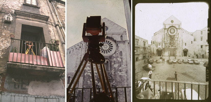
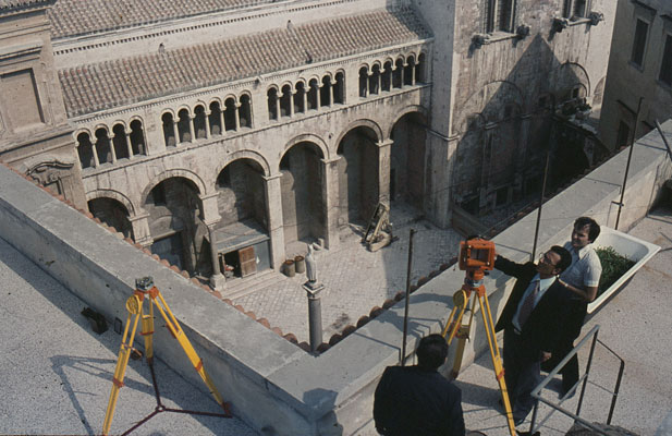
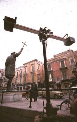
Photogrammetric shooting
It is known that to obtain a stereo photograph it is sufficient to make two normal photographic shots of the same object from two distinct points of view: in reality with this we simply obtain the stereo effect, but, if we want the image of the photographed object to result in scale, we will, after having clarified the purposes of the recovery, respect some basic rules.
- The base. If the internal and external orientation of the two beams projecting the image are kept unchanged (return orientation equal to that of shooting), the scale of the optical model is given by the relationship between the return base and the shooting base. In the case of simple stereo observation, the return base corresponds to the interpupillary distance (the average value of which we can consider 6.5 cm) and the optical model will be greater, equal or less than the original if, respectively, the shooting base will be less, equal or greater than the same interpupillary distance. The aspiration to provide the observer with a model that is perfectly the same as the original, has guided the builders in creating stereo cameras with two lenses placed at a reciprocal distance equal to the interpupillary one. These machines have not been very successful, this not because of the apparent difficulty of observing the photographs they provide, as some believe, but rather because the advantages of the photographs obtained with them, compared to those provided by common single-chamber cameras, are only highlighted in the case of objects photographed from a short distance, while they become negligible or null in panoramic photographs. To realize the real importance of stereo photography in dimensional analysis, it is sufficient to photograph the objects with a suitable shooting base to provide a scale model that can be observed at a distance of no more than one meter. There is no doubt that, having the possibility, we would prefer to carry out, for example, the dimensional analysis of a fly on its model twenty times larger and that of a building on a model one hundred or two hundred times smaller. The reasons that determine these preferences are to be found essentially in the fact that by engaging, with the object observed, the entire visual field at a distance not exceeding one meter, our brain can carry out the dimensional analysis in an area where it can not only use triangulation, which can be performed with visual axes, but the results of the obtained measurements are more reliable because they are continuously subjected to verification operations. We must not forget, in fact, that in this area we do not make mistakes in bringing our hands to the objects we want to take, precisely for the precision with which their position has been detected and that this high degree of precision has been achieved thanks to a continuous alternation (since childhood) of the relevant operations (identification of the object) with those of verification (taking the object). In the event that the visual field is totally engaged at a great distance, the positions of relief by the brain are still carried out with triangulations, but with a too small base. Basically the difference between the two perspectives obtained from the two points of view becomes imperceptible, until the stereo effect is canceled. To know numerically the optimal value of the base of recovery it is sufficient to keep in mind that:
- the minimum viewing distance of the model must not be less than 25 cm. and for this to be possible, the relationship between the shooting base and the closest point of the photographed object must not differ, as a numerical value, from the ratio between the interpupillary distance and said minimum observation distance;
- the maximum distance of the points of the model, object of observation, must not exceed the radius of action of the arm, so the ratio between the shooting base and the distance of the furthest point of the photographed object must not deviate, always as a value numerical, from the ratio between the interpupillary base and the maximum observation distance (arm range).
By replacing the respective numerical values it can be stated, with the necessary approximation, that the base of recovery must be between 1/5 of the distance of the closest point, object of the recovery, and 1/20 of the distance of the farthest one and, again more simply, 1/10 of the average distance of the set of points photographed.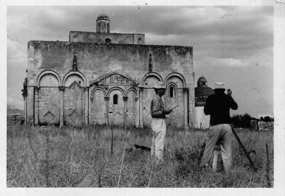


click to enlarge - The camera. The choice of the camera, with which you intend to perform stereo photography, is essentially conditioned by the scale of reproduction of the model and by the precision that it is considered possible to achieve in the dimensional analysis; the higher the degree of precision to be achieved, the more faithfully the model must reproduce the original. The conditions to be met to obtain a photographic image in scale are two:
- possibility of reconstructing, in space, the beam of rays with which the photographic image is projected in each shot (internal orientation);
- possibility of connecting the two reconstructed beams in full compliance with the conditions existing during the recovery operations (external orientation).
The following two cases should be distinguished:
1) the stereo image must be simply observed and is intended to provide a broad relief;
2) the stereo image must reproduce the photographed object with high precision, in a certain scale.
In the first case the two orientations (internal and external) can be determined and reconstructed with approximation and any camera can be used. In the second case, special equipment is used, which go by the name of "metric cameras" and which differ from common cameras in the following characteristics:
- the distance between the center of projection and the plane of the projected image (main distance) is known with the precision of the hundredth of a millimeter;
- in addition to being corrected for the entire visible and infrared spectrum, the objective has a high resolving power and negligible distortion;
- the support framework, against which the sensitive material is pressed, has two or four references, reproducible on the frame, which precisely identify the main point, that is the intersection point of the plane-frame with the perpendicular conducted by the projection center (main beam); - The orientation. For the purpose of reconstructing the optical model, what matters is not so much the arrangement of the cameras at the time of shooting, but the perfect knowledge of this arrangement; but in practice, in addition to limiting the height difference between the station points within 10% of the base (to ensure good vertical coverage), you can only choose from the three provisions listed below.
1. Converging axes. In order to optimize the analysis of the optical model, it is reduced to such dimensions that it can be observed at a distance greater than 25 cm and less than 1m: in these conditions the visual rays describe two bundles of straight lines, the axes of which are convergent and, Logically, the optical axes of the chambers should form the same angle. It is actually a purely theoretical reasoning, since the metric chamber does not present the automatism enjoyed by the eye. For example, when we observe directly an object of the same size as the optical model and placed at its same distance, the eye is able to select only what is of interest, thanks to the type of focus and the particular sensitive surface with which it is equipped. The metric camera, on the contrary, also clearly reproduces what is placed behind the object, so, in the case of shooting with converging axes, the background (which appears behind the object) can be different on the two frames and disturb the vision stereo. There are also numerous other drawbacks (including the particular arrangement of the frames being returned) which advise against the practical application of this orientation.
2. Axes orthogonal to the base. It is the type of orientation (more commonly called "normal case") that we will consider. Among the advantages that it presents are:
- the simplicity of the mathematical formulas with which it is possible to obtain the spatial coordinates of all the visible points of the photographed object;
- the arrangement of the frames being returned (both optically and graphically-numerically).
Compared to shooting with convergent axes, the normal case presents the drawback of not using the entire surface of the frames (due to the partial longitudinal covering which decreases with increasing base) but this is a problem of little importance which, however, it can be solved by resorting to lateral decentralization.
3 Oblique and parallel axes. If the shooting distance is very small compared to the size of the object photographed and to the focal length of the camera used (or when the presence of obstacles prevents placing the shooting equipment in front of the object to be photographed), it is possible to tilt the axes optics of the cameras with respect to the base, keeping their parallelism. In this case, the base value will not be given by the distance between the two station points, but by the distance between the axes themselves.
- The project. When the recovery is intended to provide a stereometric optical model, the preparation of a "recovery project" is considered essential. It is a "tare" that architectural photogrammetry has inherited from the consanguine cartographic aerial photogrammetry, where the purpose (the cartography) is quite clear and consequently the editing is possible. In the case of the architectural survey, on the other hand, by resorting to the same methodology, there is the risk of finalizing the shooting to the preparation of plans and prospects without meaning. To convince yourself, think of the simple photograph of a child taken in any automatic photo booth or by a good photographer. What is the difference? In the first case, the existence of a precise recovery project (point of view, objective, distance, exposure, etc.) carried out with an industrial mentality is certain! But in the second case? Who would dare ask the photographer for the shooting project? The comparison between the two photographs suggests the comparison that Le Corbusier made between the Parthenon and the car: both are selected products, the result of the continuous search for perfection, which however has ceased in architecture, so much so that today we have no "Parthenon" to show! In our case the "cabin", in taking the photograph, takes care to verify only if the user has inserted the coin, while the photographer adapts the shooting (objective, sensitive material, format etc.) to the subject only after having carefully studied it and reaches the final result after a series of attempts. So, can we say that the photographer does not plan the shot? How does the shooting project, according to which the photo booth was programmed, differ from that of the photographer? We can simply say that the cabin adapts the subject to the shot, while the photographer adapts the shot to the subject (for the moment it is better to ignore those people who behave like the cabins!). From the above it is clear that to plan the recovery it is not enough to fix only the station points! If it concerns buildings or urban environments, it is necessary to consider them as living beings, which must be photographed at the right time, from the right point of view and only after having become familiar with them. Just as any X-ray of the human body is the result of the collaboration between doctor and radiologist, the stereo shot comes from the close collaboration between the photogrammetric operator and the user of the shot itself, and for this to be possible, one must understand the problems of the other and vice versa. In the case of an architectural or urban survey, the recovery project is an integral part of the architectural or urban plan. It is intended to document the state of the places before, during and after the transformation of the building or the environment affected by the intervention itself, so as to allow the updating of the relative documentary sheet. The architect, as user of the survey, if he cannot participate in the shooting operations, is required to provide the photogrammetric operator with a series of information relating to:
- focal length of the metric chamber to be used;
- format-image and type of film;
- type of sensitive emulsion;
- framing, therefore point-stations and approximate inclination of the optical axis;
- exposure and aperture, therefore depth of field;
- number of shots;
- details of major interest, which must be indicated with precision on the photographs.
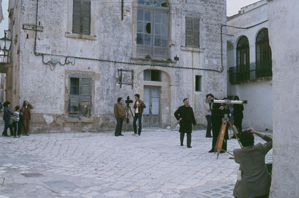
Based on this information, it is not certain that the operator can devote himself exclusively to the technical resolution of shooting operations. The time interval, between the design phase and the execution phase, may have improved or worsened the environmental situation (parked cars, more or less bare trees, scaffolding, road works etc.) and in this case it is up to the operator to adapt the recovery taking care to keep the contents unchanged. Therefore, the training of the photogrammetric operator must be cultural as well as technical. - The operations. A clear distinction (which must necessarily be mentioned) exists between stereophotogrammetric and stereophotogrammetric survey: the latter is made up of a set of recordings aimed at documenting an object or part of it. While for the stereophotogrammetric survey there may be a design phase, the recovery can only be designed on site and at the time of shooting, especially because of the unpredictable moving obstacles, which can determine on the photograph the "shadow areas". That said, we can believe that the sequence of shooting operations is as follows:
- identification of the object to be photographed and analysis of the same;
- choice of the station points and the base according to both the acquisition of the requested information and the return scale;
- arrangement of the room in the chosen points and verification of the shot;
- photographic shot, simultaneous or successive, from both points;
- survey of control points.
The overall duration of these operations depends on the type of equipment used and can be short-lived (around ten minutes) or prolonged over time (a few hours).
�
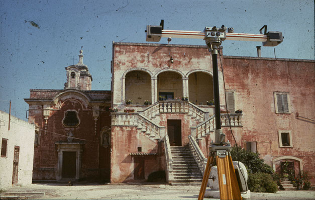
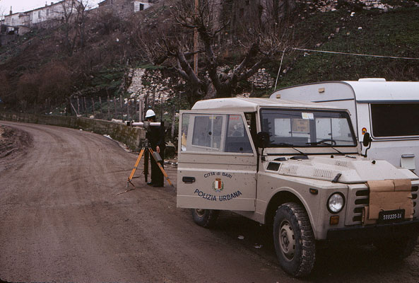
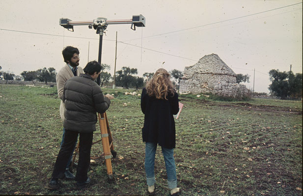
1. Shooting with phototeodolite. Excluding the case of the simultaneous use of two phototeodolites placed in the two station points, we assume that the metric chamber is coupled to an electronic theodolite. Since theodolite can accurately supply all zenith and azimuth angles, the sequence of operations should be as follows:
- identification of the recovery points;
- mounting the tripods in said points;
- verification of the framing obtainable from the chosen shooting points;
- identification of at least three pairs of points on the object, indispensable for checking the measurements in the three orthogonal directions;
- detection of these points with theodolite;
- measurement of the base;
- photographic recovery from the two station points and detection of the external orientation. If the "normal case" is used, the shot must be checked after arranging the optical axis of the camera orthogonally to the base (for any corrections to the shot itself, it will be necessary to move the other point-station and then proceed by approximation following).
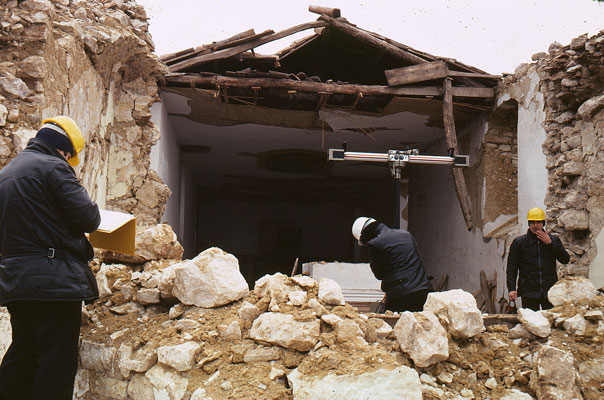
2. Shooting with single-chamber. When it is possible to do without theodolite when surveying the control points and the base, the metric chamber is mounted on a support which allows (even if simply on predetermined positions) the determination of the external orientation. In this case, the recovery operations are simplified considerably and include:
- identification of the recovery points;
- verification of the framing and possible adjustment of the station points;
- taken from each point-station, after checking the orthogonality between the optical axis and the base (in the eventual adoption of the "normal case");
- measurement of the base;
- survey of the control points directly or, if necessary, by using the distance meter.
The recovery can be carried out, with obvious advantages, with two synchronized metric chambers.
3. Shooting with stereocamera. Shooting with the stereometric chamber does not allow to adapt the base to the shooting distance, but has the advantage of considerable speed; in fact, it involves the following operations:
- choice of the point-station, in which the stereocamera is to be mounted;
- setting up the stereocamera;
- verification of the shot and photographic shot.
The stereocamera allows the elimination of the relief of the control points since the relative orientation (as well as the internal one) is known thanks to a periodic calibration carried out on the test field. The number of operations listed above can be further reduced if it only affects the dimensional analysis of the photographed object and not its orientation: in this case the shooting time does not differ from that of a common photographic shot. - The testing. This is a phase (intended only for stereometric shots) which aims to verify:
- the legibility of the photographic images and, therefore, the successful acquisition of the requested information;
- recording on the frames of the references determining the internal orientation;
- data relating to external orientation;
- the survey of the control points.
In the case of the stereometric chamber, the verification of the relief of the control points is replaced by the calibration of the stereocamera itself. The operations listed above assume that, when shooting, the shot was taken from both points of view and that, therefore, the stereo vision cannot be disturbed by the presence of harmful close-ups. - The utilization. By means of the pair of stereo or sterometric frames, the image of the object taken can be archived and used after some time, to be analyzed in stereovision or represented in graphic or numerical language. Currently in architecture and urban planning it is used simply to derive floor plans or altimetries; but it is actually an underutilization, if one considers both the large amount of information contained in the photographic image and the data processing programs, by means of an electronic calculator, existing on the market. In the urban planning sector, for example, it is possible to detect a historic center (by aerial and terrestrial photogrammetry); analyze the frames relating to a road or square; perform the numerical survey of the facades of the buildings; store data; obtain static representations (orthogonal projections, axonometric projections, perspectives); carry out design interventions and verify the environmental insertion by means of dynamic representations (movement of the observation point along selected paths and at the desired altitude). Stereo photography (and therefore stereophotogrammetric survey) does not represent an alternative to traditional survey, but a new method of analysis of the territorial reality: it provides the designer with a database whose management is possible only with the use of the electronic calculator. The design of a simple window frame can take place in the light of an accurate analysis of all the window frames made. Of these, the database can provide information relating to size, structure, operation, heat transmission, ventilation, water tightness, etc. During the design phase, the new frame can be tested with simulated tests, then be made in the form of a prototype to be subjected to the various test tests. The results may in turn be stored in order to represent the starting point in the design of other fixtures. With the extension of the same design methodology to all the compositional elements of the house, stereo photography will allow the creation of a building use and maintenance booklet.